The term is ambiguous terms.
1.OBD
English name: OpticalBeamDeflection
Chinese name: deflecting a light beam
1, the basic concept of
Laser scanning confocal microscope imaging principle and composed of a total of the meaning is to focus the imaging information other than the focal area of the filter, so it does not show in the final image result, the light is first focused on the point or line, and then the plane to be observed is scanned by the light focusing region other than the detection probe filters to remove. Laser scanning confocal microscope imaging principle, a laser beam emitted from the laser through the beam expander lens and the beam shaping mirror into a parallel beam bundle of a large, long-pass dichroic mirror deflects the beam of radiation 90 °, the objective lens is converged through the objective lens focus, the fluorescent substance in the sample fluorescence emission in various directions at an excitation laser, a portion of the fluorescence through the objective lens, a long-pass dichroic mirror radiation, a focusing lens, a pinhole at the focal point of a converging focusing lens, and received by the detector , a photomultiplier tube (PMT) collected and amplified signal, and then subjected to signal processing, the computer to the image point manner imaging point on the screen, scanned by the optical path of the scanning system over the entire sample to produce a on the display full image, this image is the focal plane of the confocal images, as long as the stage is moved along the Z-axis, the sample was moved to a new confocal surface layer, and the new dimension of the sample image on a display, with the Z-axis movement section does not, can obtain different levels of continuous light section image samples. We will continuously laser scanning confocal optical microscope image of the cut fibers compared to CT, the continuous light from the image may be cut at a three-dimensional simulation recombinant sample.  1
1
2, the practical application
 the OBD
By using the focusing excellent kilowatt CO2 laser can be greatly improve the welding speed. Traditional laser related to thisHigh machine dynamics requires only a few can meet the laser device. In particular, the orbital motion is severely bent, such as small-sized processing component structure is more problematic.
Even the best laser kinetics, such as a two-dimensional linear cutting apparatus functioning only to obtain orbital velocity of approximately 20m / min when cutting 10mm diameter circle structure. Small radius of curvature can reduce the accuracy of the track structure or reduced speed.
Solution Way
Alternatively supplement conventional laser processing machine and a normal Cartesian-type child or method is to use a cross-shaft chain laser beam on a workpiece moving the beam deflection system. When to replace the common welding and cutting head with the system, an operating system (gantry crane or an industrial robot) can only assume the role of basic positioning and processing head member, the actual operation of the intake amount of rotation by the machining head beam deflection system Reflector in . Since the light polarizer mass, even such a beam is rotated at a high precision in particular propulsion speed (600m / min).
At present, such a beam deflection system for laser marking or low laser power (hundreds of watts) welding. Here the laser beam focused by a lens, the two mutually perpendicular, by the driving of the galvano scanner polarizer beam is focused on moving workpiece. The structure and operation principle of the deflection system only determines the distance between the deflection member and further up to the determined operating range. Since the focus is moved in an annular surface, which determines the occurrence of aberration in principle. This deflection angle shape and size to be processed, i.e., in the laser beam about the possible use restrictions. Flat-field lens can be avoided using this aberration, planar workpiece can be processed with a constant beam intensity determined in the workplace.
As a result of the lens member and the optical scanning mirror, a beam deflection system of commercial suppliers will be transmitted in several hundred watts of laser power limitations, and is generally for machinery millimetric for deep welding, the take a few dry laser watts of power.
High power laser beam deflection system in the
Materials and Fischer Fraunhofer – Institute Cambodia exit beam deflection technique for this purpose the development of a system for high-power laser when to 4kW CO2 laser processing. This helps to achieve the high-tech machining feed rate into industrial applications.
Processing systemSystem by the beam deflecting unit having a galvo scanner and a parabolic mirror focusing system has a composition, the parabolic mirror can be dynamically tracked completed by additional reflector focus. This produces a hardware control program controls the basic blocks formed and special processing tasks modular PC card, the system also uses a beam monitor additional components to be improved. Further, in order to transmit a high power laser, for all of the optical components are cooled.
Application Example
One example of an alternative-axis motion system is to use a one-dimensional beam deflector widget laser spot welding, where the laser power and pulse sequences simultaneously controlled. Since 1977, the industrial sector in 16 popular machining the weld has been achieved within 500ms. So in a multi-stage processing station 8 may be welded into a circular ring bent strip. Each year about 20 million of these weldments.
Another field of application is likely to succeed, nut, pin, welding and the like into the compositions tube member. The 2.5mm diameter small tube welded into the plate. Welding time is about 100ms. Here, the control determines the position of the sensor need to be the next pipe to avoid since the position tolerances of the entire twisting member.
In principle, the graphics processing track, especially when machining a small diameter, can be achieved with other systems, but the use of beam deflection systems can be virtually unlimited diversification machining shape. Because for beam deflection system, unlike the conventional systems is that motion, generated during welding to maintain a constant feed rate, the geometry to be machined not play an important role, and the machining head opposite precise positioning member touches important.
3, laboratory oscilloscope
as long as the normal scanning tool, it tells the user the engine operating conditions, but the reader still can not “see” the problem or because of “false signal” occurs too quickly, scan tool not show up, or simply not OBDⅡ system programmed to identify this difference. In view of this situation, using a laboratory oscilloscope is very effective. Oscilloscope desktop, there are hand-held. Fault with decades old analog oscilloscope check the ignition system, but it is completely modern laboratory oscilloscopes are different types. TraditionSignal requirements analog oscilloscope shows a repetitive periodic signal, and laboratory oscilloscopes real-time display of this signal. Because of the high sampling frequency, it is important details for each signal are shown, such a high speed signal may be any recognizable cause failure during engine operation. If desired, any time can be re-read the waveform, since these waveforms can be stored in memory. A typical modern laboratory oscilloscope has a two-line or function. That can be seen that while two or more separate signals on a screen. Such influence can be observed how a signal another signal. E.g. oxygen sensor voltage signal can be input to the channel A, the injector pulse input to the channel B, and then to observe whether the impulse response change in the oxygen sensor signal. Lab scope can be regarded as a high-speed voltmeter visible. Signal waveform can be seen clearly in the interference pattern to capture the moment, is not normal waveform spikes and noise in the measured components. A point worth noting: OBD emissions of non-compliance only when the alarm, but if oil failed to install OBD will be useless. It is understood that the domestic automobile joint venture plant in recent years to introduce some Chinese models will be sold in Europe over the same period, they are equipped in the beginning of the production of OBD and reached the Euro Ⅲ even the Euro IV standard, minus the OBD or off after a domestic big reason is to avoid the failure of oil caused by the police, leading to unnecessary trouble.
4, OBD introduced problems facing
closely related to the four main aspects of the introduction of OBD, and use of the environment, fuel characteristics, driving habits, vehicle status. Any one part of the short board, will affect the expansion and application of OBD. The introduction of OBD technology, the following relevant supporting conditions corresponding increase: support for fuel quality, vehicle maintenance skills, consistency related parts and improve the level of the driver, improving OBD technology itself and all sectors of society. I believe that within a certain period of time, China’s OBD technology is a process of adaptation and the introduction of digestion and absorption. Because OBD technology, not only related with the car itself, but also the number of links associated with other fuel and driver, etc., OBD technology introduction and expansion, is the automobile industry chainA test and improve.
5, OBD development
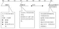
OBD technology originated in the United States, the early 80’s OBD technology, is to remind the driver failure or malfunction occurring by appropriate technical means. The EU and Japan, the introduction of OBD technology after 2000, 04 years later, OBD automotive technology developed countries to take the third stage.
 1
1
 2
2
n
project in Europe and the USA and the detection limit OBD aspects, there are some differences, the specific differences content not elaborate. Before the United States find fault OBD purpose of monitoring is to become a high-emission vehicle standards; the purpose of the European OBD monitoring is to find high-emission vehicles. Our import OBD technology, equivalent to the relevant provisions of OBD systems in Europe after three stages.
after the author and automotive technicians determine, Euro III emission standards does not mean OBD, install OBD December 1 implementation of Beijing’s enforcement policy, vehicles + OBD standard Euro III.
OBD need to declare the vehicle to install OBD, we need to apply a systematic process, but also requires companies to install OBD vehicle carried out a number of tests, provide compliance data to the relevant authorities (currently three projects will be seized oxygen sensor failure verification, the catalytic converter fails verification, validation fire), usually 10 months period. Install OBD vehicles, the need to re-apply announcement of the vehicle. OBD high research and development costs, if scale production, single-sharing technology costs will be reduced.
2.OBD
English name: On-Board Diagnostics
Chinese name: automatic on-board diagnostic systems
6, OBD ⅱ standardization
Design
OBDⅡ procedures required to avoid confusion between systems, which not only requires the use of a standard 16-pin diagnostic interface, but also the use of the particular coding and components described in the manufacturer’s file, which is to achieve the following harmonization and standardization. Means
General terms and acronyms
For example, to provide crankshaft position and speed information for the computer is called a crank position sensor, are abbreviated “CKP”, it is referred to as a unified computer “PCM”.
General data Diagnostics Interface
Each car is equipped with a standard 16-pin diagnostic interface shape and size, the same signal distribution of each pin, and at the same position, mounted under the dashboard, instrument tray on the left and the center line of the car somewhere between the right 300mm. It should be noted that some of the terminals are diagnostic interface, designated as a specific signal as shown in the table. While other terminals may allow manufacturers to use, or not used in current car models.
Generic Diagnostic Test Mode
test patterns, are common for all cars OBDⅡ using OBDⅡ scan tool can be tested.
The Common Scan Tool
scan tool OBDⅡ meet the requirements, must pass through to access and interpret any vehicle emissions related diagnostic trouble codes, scan tool in contact with the wire harness may be a standard 16-pin connector.
General diagnostic trouble code
while in Shanghai Buick, Guangzhou Accord other car fault diagnosis, self-diagnosis system can display standard OBDⅡ fault code, such as “PO125”, “PO204”, respectively representatives when the speed signal does not reach the engine 10 deg.] C 5min injector 4 and the output driver in response to the control signal incorrectly. 5 SAEJ2010 a predetermined standard fault code, bit 1 is the letter followed four numbers. The first letter represents the set of system fault codes. There currently allocated four letters: “P” representative of the power system, “B” representative of the body, “C” on behalf of the chassis, “u” system representative of undefined. The first two characters are 1, 2 or 3 with the following meaning: 0 – generic fault codes SAE (Society of Automotive Engineers) defined: 1– car manufacturers extended the definition of fault codes; 2 or 3– with the system different characters (P, B, C or U) differ. powerSystem fault code (P), 2 or 3 in SAE reserved for future use; vehicle body or chassis fault codes reserved for the factory 2, the vehicle body or chassis fault code 3 retained by SAE. Bit 3 shows the character of the system failure: 1– fuel metering or air fault; fault 2– fuel metering or air; 3– engine misfire or an ignition failure; 4– secondary emission control system failure; 5– automobile or idling control system failure; 6– computer or an output circuit fault. 7– transmission control system; 8– transmission control system. The last two characters represent triggers a fault code. Various sensors, actuators and digital circuits assigned different sections, a small section of a digital representation of general fault, i.e. general fault codes; spreading codes with a higher number provides more specific information, such as low voltage or high, slow response, or out of range signal.
Standardization Agreement
requires the manufacturer to use the same language multiplex communication, communication between the PCM and its sensors and actuators, and diagnostic information between the sending and receiving diagnostic tools. OBDⅡ standard engine management system for each of the monitored receiving circuit, the operating conditions specifically set period of warming, the driving cycle, OBDⅡ stroke, OBDⅡ driving period and similar conditions, the failure is detected in monitoring the sequence, the position of the fault code, fault light on and off, and the fault code erasing. Here, the operation sequence is a monitoring process, is used to test a predetermined operating system functions or components. Example, a computer can be opened at the time of deceleration or closes the EGR valve, and monitors the MAP sensor to observe the EGR valve is working; or while cruising, the computer opens or closes the canister purge to observed signals oxygen sensor, so can test simultaneously two members.
7, detailed information
This system will monitor the operating conditions of the engine at any time whether excessive vehicle exhaust, once exceeded, a warning will be issued immediately. When the system fails, the failure (MIL) lamp or check engine (Check Engine) warning light, while the powertrain control module (PCM) fault information stored in the memory, it may be by certain proceduresFault code read from the PCM. The prompt fault code, maintenance personnel can quickly and accurately determine the nature and location of the fault.
8, relevant information
2006 December 1, Beijing has banned the installation of the vehicle does not prohibit the sale of OBD in Beijing.
In July 2008, have been implemented nationwide installation of vehicle OBD.
 OBDII automotive diagnostic socket 16-pin interface definition
9, the rest of the
of the rest of the No on OBD be required.
[OBD in PON] OBD (Opticalbranchingdevice) some optical splitter also called the POS splitter