1, structural features
 loader shaft structure The heavy-duty truck drive shaft in the form of different types of different options. Generally, in the form of 4 × 2 driving a main drive shaft only automobiles. 6 × 4 in the form of automobiles driven intermediate shaft, the main drive shaft and the rear axle shaft. 6 × 6 drive type vehicle not only the intermediate transmission shaft, the main drive shaft and the rear axle drive shaft, but also the front axle drive shaft. In the middle of the long wheelbase of the vehicle provided with the drive shaft intermediate the drive shaft is generally supported. It is a support frame, the support bearing and a rubber composition.
axis of the shaft is a tube, and a telescopic joint composition. Telescopic automatically adjust change in the distance between the transmission and drive axle. Is to ensure that two joint axes angle change transmission output shaft and the drive axle input shaft, two speed transmission and to achieve an isometric axes. Usually universal joint cross shaft, the cross and flange yoke bearings and other components. Steyr series of heavy vehicles used in the propeller shaft universal joint cross shaft in roller bearings, with a short and thick cross shaft can transmit high torque. Belleville springs is provided in the bearing end face in the pressing roller. Increases the cross shaft end surface reinforced nylon pad having a spiral groove, prevent a large rotation angle or a large power is transmitted from the sintering time.
configuration of a conventional telescopic shaft is a splined sleeve welded together with the flange yoke, the spline shaft is welded to the driveshaft tube. GWB’s propeller shaft and a change in the traditional structure, the spline shaft sleeve and welded into one pipe, the spline shaft is integrally formed with the flange yoke. And the large rectangular spline into short pressure angle involute splines, so as to enhance the strength and easy extrusion, large torque is required to adapt to operating conditions. Telescopic spline shaft sleeve and the dental surface, the overall coating layer of nylon soaked material, not only increases the wear resistance and self-lubricating properties, but also reduces the shock load damage to the drive shaft, to improve the buffering capacity.
This type of spline shaft flange adds a tubular outer protective sealing sheath, the end portion of the protective sleeve is provided two urethane rubber seal, the telescopic sleeve is formed a completely sealed factory space, the telescopic spline shaft from outside dust erosion, not only dust and rust. Therefore, when assembling the disposable apply grease to the spline shaft and the sleeve, completely meet the requirements, does not require lubrication nipple installed, reducing maintenance content.
is a high speed shaft, bearing little rotating body balancing prisoners where it is essential. General propeller shaft balancing test should be carried out at the factory, and has been adjusted on the balancing machine. Therefore, a group supporting the drive shaft is manufactured, should pay special attention in use.
2. Use Interpretation
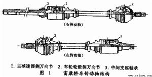
 by an outer drive shaft joint drive shaft assembly (RF section), the inner gimbal (VL section) and the spline shaft composition, the RF section and VL section are ball type constant velocity joint. VL section connected to the differential drive shaft flange by bolts, the RF section is connected by a spline shaft front end portion alien wheel, the left and right front wheels respectively, by a constant velocity joint drive shaft .
First, the shaft (axle) assembly removably: (axle) decomposition of the drive shaft assembly.
(a) Removal
(1) When the wheel, the shaft and the hub unscrewing the tightening nut.
(2) Remove the fastening bolts on the flange shaft.
(3) separated from the shaft and the flange.
(4) drawn from the wheel shaft bearing shell; or by pressure means V.A.G1389 drawn shaft.
Note: When removing the drive shaft, the hub must not be heated, otherwise it will damage the wheel bearing, the puller should be used in principle. After the shaft removed, should be installed on a shaft connected to the drive shaft in place, to prevent the vehicle moving relieved shaft, front axle bearing assembly damage.
(b) mounting
(1) is screwed on the net oil and the spline shaft, coated with lithium grease.
(2) coated with a repellant D6 circle on the outer gimbal 5mm (RF section) spline, and then loaded on the transmission shaft spline bushing. 60min rear propeller shaft should stop after repellant coating installation before you can use the car.
(3) the ball stud reassembled in the original position, and tighten the nut. When installing the ball stud, the bellows can not damage the sheath.
(4) necessaryCheck the front wheel camber.
(5) with the rear wheel, the tightening of the hub fixing nut.
Second, the joint removal
(1) The clip with a hacksaw joint dust cover on the sawing, the dust cover is removed .
(2) an outer joint tap-down force (RF section) from the hammer shaft with a light metal.
(3) Removing a spring lock ring.
(4) an inner gimbal pressure (VL section).
(5) before etching pen or break electrical whetstone indicated position on the spider and the ball cage alien wheel.
Third, the decomposition of the joint
(a) an outer joint (RF section)
(1 ) and the rotary star wheel cage, the ball sequentially removed.
(2) until the forced rotation of the ball cage with two square holes linear alien wheel, the wheel is removed together with the alien cage together.
(3) rotating the sector gear goal cage inner square hole star wheel, the star wheel is then removed from the cage.
the (two) cardan (VL Section)
(1) the star wheel rotates with the cage, the ball pressing the ball cage. Note: in the case was a star wheel and optional, are not interchangeable.
(2) Remove the ball from the ball cage groove above the star wheel.
(c) checking components
(1) Check the alien wheel, the star wheel, and the ball cage with the presence or absence of the recess wear.
(2) 6 at each ball joint requires a certain tolerances and, together with the star wheel into a set of mating member.
(3) If the joint has obvious gap is too large, joint must be replaced. If the universal joint was smooth lossless or to see the ball in the run, it does not replace the universal joint.
(4) Check the dust cover is broken, ring and seat is invalid, or should be replaced.
Fourth, the gimbal assembly
 RCD-30 drive shaft balancing machine (a) theGimbal (VL Section)
(1) star wheel alignment groove embedded within the cage, the cage position within the star wheel does not matter.
(2) pressing the ball cage goal, and injecting grease G6 90g.
(3) the ball and the cage with a vertical load of the wheel housing alien. Note: after the rotation, on a wide interval alien wheel should be aligned at narrow intervals on the inner b star wheel, rotatably fitted in place so that the cage; chamfer on the inner diameter of the star wheel (splines) must be aligned round the alien the large diameter end.
(4) the star wheel twisted, so that the star wheel can be transferred out of the cage, and the steel ball in the ball groove alien wheel cooperating with a sufficient gap.
(5) pressed firmly pulling the cage, the inner star wheel with balls completely alien into the wheel.
(6) the star wheel hand pushed back and forth within the axial range, if flexible, expressed correctly assembled.
(b) an outer joint
(1) washing the parts with gasoline.
(2) half of the total amount of the grease G6 (45g) is injected into the joint.
(3) together with the cage within the star wheel loaded with alien wheel.
(4) diagonally alternately pressed into the ball, must remain in that position of the star wheel in the cage and alien wheel.
(5) the spring ring into the star wheel lock.
(6) The remaining grease into the joint.
(7) the star wheel hand pushed back and forth within the axial range, check for proper installation.
Fifth, the inner and outer gimbal mounting
(1) mounted on the drive shaft guard.
(2) properly installed disc seat.
(3) press-fitted to the inner gimbal shaft. The disc seat fit, chamfer on the inner star wheel diameter (splines) must face the drive shaft on the shoulder.
(4) spring-mounted locking collar.
(5) mounted on the outer gimbal.
(6) when the dust cover mounted on a universal joint dust cover often squeezed. Thereby generating a certain vacuum within the dust cover, it generates a suction off the vehicle is travelingmark. Therefore, after mounting the dust cover small diameter, slightly point the gas filling, the pressure balance, no wrinkles.
(7) with a clamp clamped dust cap. The new model used pliers to V.A.G1275.
3, the balance shaft
Balance shaft 6 has the following major role:
1, improve product quality and configuration of the rotor;
2, reducing the noise;
3, reducing the vibration;
4, to try to improve the life of the support member (bearing);
5, reduced user discomfort sense;
6, to reduce power consumption of the product.
4, common failure
 Fukang cars drive shaft propeller shaft mechanical damage, wear, deformation and loss of dynamic balance, will result in a moving car the generation of abnormal noise and vibrations can cause serious damage to associated components. Cars, the issue at the start or hard acceleration “Gordon” sound, and clearly show the feeling of looseness of parts, if not the drive axle drive gear Songkuang is obviously Songkuang drive shaft parts. Songkuang site is nothing more than a cross bearing universal joint or flange yoke with steel bowl, telescopic spline shaft and spline sleeve. Generally, the cross shaft and the bearing shaft diameter should not exceed 0.13mm Kuang, a telescopic spline shaft and spline sleeve meshing clearance should not exceed 0.3mm. It should be repaired or replaced to use more than the limit.
If the cars occurs chassis “buzzing” sound, and the higher the speed, the louder. This is usually due to a universal joint cross shaft bearing wear and looseness, the intermediate shaft bearing wear, damage or intermediate rubber bearing hanger loose, due to the fixed position or not due to the hanger.
6 × 4 car during heavy load, especially with occasionally bumps percussion issued, should check whether the rear axle balancer shaft displacement interfere with the drive shaft. If the car running with the increase in vehicle speed and the noise increases, and accompanied by jitter, which is usually due to loss of balance due to the drive shaft. This vibration in the cab feel the most obvious. Balancing shaft unbalance amount should be less than 100g.cm.
Balancing shaft failure a serious cause damage to associated components. The most common are fatigue cracks and damage to the clutch housing of the intermediate rubber bearing.
The central suspension shaft mounted in maintenance is important. If improperly installed hanger position, it will increase the drive shaft running resistance and noise, leading to early bearing damage. When reinstalling the hanger, the first hanger fixing bolt not tightened, the car wheels with the ground jack fragmented, downshift, slowly rotating propeller shaft and the drive shaft hanger automatic alignment and then fixed hanger bolting.
5, use and maintenance
 gum hanging shaft to ensure proper operation of the drive shaft, extending its life in use should be noted:
1, non car started with a high gear.
2, Meng lift the clutch pedal is prohibited.
3, non-automotive overloading, speeding.
4, the drive shaft should always check the working conditions.
5, should always check the tightness of the hanger shaft, the supporting rubber is damaged, whether all joints Songkuang shaft, the drive shaft is deformed.
6, should often universal joint cross bearings for lubrication, the summer should be injected into lithium grease No. 3, No. 2 winter lithium grease injection. 7, in order to ensure the balancing shaft, a balance should always pay attention to whether the sealing off lug. The new support provided by a drive shaft assembly, the loading should be noted that the telescopic shaft assembly new marker sleeves should ensure a flange yoke in a plane. Disassembling the drive shaft in the maintenance should be kept constant during the original assembly relationship printing assembly marking telescopic shaft with the flange, to prepare for re-assembly.
6, the structure and working environment
The main shaft assembly by the drive shaft and welded at both ends of the spline shaft and yoke components. Generally provided with a sliding shaft by the spline and the spline shaft sliding fork composition to effect changes in the length of the transmission. To reduce the axial sliding resistance and the sliding splines wear, sometimes spline teeth or spray phosphating layers of nylon; others into the other needle, roller or ball spline grooves are rolling elements, rolling friction instead of sliding friction, improve the transmission efficiency. However, this structure is more complex and costly. Sometimes serious impact load to the transmission, the drive shaft having an elasticity also be employed. Spline should be lubricated and dust control measures on the transmission shaft, spline teeth and keyway gap should not be too large, and should mark the corresponding assembly, so as not to damage shaft assembly installed wrong balancing.
The length and angle of the drive shaft and the scope thereof is determined by the change in the total arrangement automotive design. The design should ensure that the length of the drive shaft at the maximum, and the shaft sleeve spline fitting length sufficient; but the minimum length does not in the top die. Shaft angle directly affects the size of the life and the universal joint cross shaft needle bearing, efficiency of the universal drive shaft and the non-uniformity of the cross.
Coupling supporting products used in a variety of different hosts, the working environment around the complex, such as temperature, humidity, water, vapor, dust, sand, oil, acid, alkaline, corrosive, brine, radiation and other conditions, It is one of the important factors that must be considered when selecting the coupling. For heat, cold, oil, acids, bases the working mass medium is generally inappropriate to use an elastic rubber material of flexible coupling member, the resilient member should be selected metal flexible coupling, e.g. diaphragm coupling, Grid couplings and so on.