1, what is the joint
 joint
joint
cardan universal joint, i.e., the English name universaljoint, achieving variable angular power transmission parts, for the need to change the drive axis position direction, it is the “joint” of the transmission member universal car drive system. In combination with a universal joint shaft, called gimbal gear. Structure and function somewhat like a universal joint of the human limbs joint, which allows the angle between the connecting part is varied within a certain range. To meet the power transmission, and the steering angle adaptation generated during operation of the vehicle caused by change up and down, is connected between the common joint front drive axle driven motor vehicle, with the axle half shafts. However, due to restrictions by the axial dimension, and requires a relatively large angle, a single universal joint shaft and the output shaft can not instantaneous angular velocity of the shaft is equal to, likely to cause vibration, mechanical damage increased, generating a lot of noise, so widely used in a variety of constant velocity joints. Front drive vehicle, each axle with two constant velocity joints, and close to the transaxle joint is a joint inner axle, the axle near the outer joint axle. The rear drive vehicle, the engine, the clutch and the transmission as a whole is mounted on the frame, and the drive axle connected to the frame by elastic suspension, having a distance therebetween, connection. Uneven road operation of the vehicle from bouncing, load change or difference of two assemblies mounted, will be such that the transmission output shaft to the drive axle gear unit input angle and distance between the axes is changed, so after driving the car gimbal transmission forms are double universal joints, drive shaft is a universal joint at each end, its role is to both ends of the drive shaft is equal to the angle, ensure the instantaneous angular velocity of the output shaft and the shaft axis is always the same. Is not constant velocity joint
is a universal joint cross shaft rigidly constant velocity joint not widely used on an automobile, to permit the adjacent constant velocity joint
 The constant velocity universal the maximum angle of intersection section
of the two axes 15 and 20 ゜ ゜. Cross-axis shown in the figure consists of a universal joint cross shaft, yoke and two universal joints four needle bearings and other components. Twenty thousand to the yoke and the holes 31 are fitted over the cross shaft 2 of two pairs of journals. So that when the driving shaft rotates, the driven shaft can rotate therewith, but also about the cross shaft swings in any direction, so thatThe need to adapt to changes in the angle and distance. 5 with needle bearing between the cross shaft journal hole and yokes, outer needle roller bearings axially positioned by a snap ring. To lubricate the bearings, cross shafts are generally safe and have re-greasing oil path leading to the journal. Lubricating oil from the injection nozzle to inject the needle bearing cross shaft journal.
rigid cross shaft joint having a simple structure, the advantages of high transmission efficiency, in the case of the two-axis angle α is not zero, the rotation speed can not pass the isocenter.
When the following two conditions are met, can be achieved by the output shaft of the transmission to the drive axle.
2,1. Overview of the power transmission between the rotating shaft
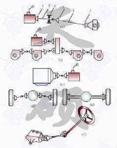 FIG structure
In the automotive and other drive train system, to achieve some or intersecting the axis of frequently changing the relative position of the transmission must be universal. Usually a universal joint transmission shaft and composition, sometimes with an intermediate bearing, mainly for some of the following positions: 1- gimbal section; 2- shaft; 3- front driveshaft; intermediate support 4- [ 123] front engine rear wheel drive transmission between the drive axle and the vehicle (see (a)) of. When a distant between the transmission and drive axle, the transmission shaft should be divided into two or even multi-stage, and setting up the intermediate support. Or between the drive axle and the drive axle of an automobile multi-axis drive between the splitter and the drive axle (see (b)). Since the deformation of the frame, between the two transmission members cause mutual axial position between the variations. FIG (c) is shown between the engine and the transmission. Independent suspension between the vehicle and the differential (see (d)). Between the steering wheel and the drive axle differential (see (e)). Power output apparatus and an automobile steering actuating mechanism (see (f)).
3,2. Joint
gimbal angle is variable to achieve power transmission parts, required for changing the position of the propeller shaft line direction.
(1) classification by jointWhether joint significant elasticity in the torsional direction can be divided into rigid joint and a flexible joint. Not rigid joint can be divided into a constant velocity joint (commonly a cross-axis), the quasi-constant velocity joint (e.g., double cardan) and the constant velocity joint (ball type Wan the festival) three.
(2) is not constant velocity joint
does not constant velocity joint 
is a universal joint cross shaft rigidly widely used on automobile the constant velocity universal joint, allowing the two axes of adjacent maximum intersection angle of 15 to 20 ゜ ゜. Cross-axis shown in the figure consists of a universal joint cross shaft, yoke and two universal joints four needle bearings and other components. Twenty thousand to the yoke and the holes 31 are fitted over the cross shaft 2 of two pairs of journals. So that when the driving shaft rotates, the driven shaft can rotate therewith, but also about the cross shaft swings in any direction, so that the need to adapt to changes in distance and angle. 5 with needle bearing between the cross shaft journal hole and yokes, outer needle roller bearings axially positioned by a snap ring. To lubricate the bearings, cross shafts are generally safe and have re-greasing oil path leading to the journal. Lubricating oil from the injection nozzle to inject the needle bearing cross shaft journal. 1- universal joint cross shaft sleeve structure; 2- cross shaft; 3- fork shaft; 4- collar; 5- bearing outer ring; 6- rigid sleeve cross shaft joint fork has a simple structure, the transmission the advantages of high efficiency, but in the case of the two-axis angle α is not zero, the rotation speed can not pass the isocenter.
When the following two conditions are met, constant velocity can be achieved by the transmission input shaft to the output shaft of the transmission drive axle: both ends of the yoke shaft in the same plane;
2) a first It is equal to the angle α2 between the joint angle α1 between two shafts and a second two-axis gimbal.
Since while driving, to the axle relative to the transmission jitter, is not possible at all times α1 = α2, in fact, can do approximately constant speed drive transmission to the drive axle. In the above transmission, the greater the crossing angle [alpha] between the axes, the more uneven the rotation shaft, the additional load generated by alternating the greater, the more negative of mechanical life, but also reduce the transmission efficiency, it is generally disposed should minimize the crossing angle between these axes.
(3) the quasi-constant velocity joint
Common quasi-constant velocity joint constant velocity joint has a quasi double-shaft and three-two, their work principles and double cross shaft universal joint constant velocityDrive principle is the same.  1,4-joint yoke section; 2- cross shaft; 3- seal; 5- spring 6- bowl; 7- double fork; 8- double ball joint is actually a formula the shaft length to a minimum reduction of the double constant velocity universal joint cross shaft gear, corresponding to double fork shaft and universal joint yoke at both ends on the same plane. When the smaller angle of intersection of the output shaft and the input shaft, the shaft axis at the intersection of two arcs on the vertical away from said close, so that the difference between α1 and α2 of small, two-axis angular speed can nearly equal, so called bis cardan subject to constant velocity joints.
4) the constant velocity joint
Currently used on car constant velocity joint joint ball cage, there is also a ball joint fork free three sections or pivot joint. The structure shown below Rzeppa joint.
Within a star sleeve 7 is splined to the drive shaft 1 is connected to the outer surface of six arcuate grooves formed in the raceway. 8, the inner surface of the spherical shell corresponding to six arcuate grooves, forming the outer raceway. Six balls 6 are mounted in the space defined by the inner and outer raceways of the six sets out, the holder 4 and is defined in the same plane. 6 by the power transmitted from the driving shaft Ball 1 (and star sets) 8 outputs a spherical shell.
1- ball type constant velocity joint drive shaft 2,5 cuff strip; 3- 4- holder housing (cage) of 6 sets of radial ball 7- (inner race ) 8- spherical shell (outer race) 9 snap ring
in the six ball constant velocity joint
all ball type constant velocity joint force transmission, carrying capacity, two axes intersecting angle may be a maximum transmit torque case 42 ゜, compact structure, easy disassembly, are widely used.
In the various sections of the constant velocity joint, ball type joint are common, with six balls which force transmission driving shaft and the driven shaft in any of the crossing angle, the balls are located between two parks at the intersection, which is located two shaft angle bisecting plane, thereby ensuring that the angular velocity of the main drive, the driven shaft.